WARNING
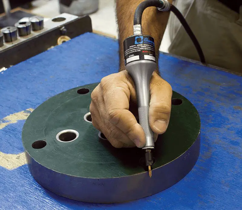
Never clamp your Air Turbine Tool® hand tool into a fixture.
Always use proper eye protection.
Read all instructions thoroughly before installation and use.
Initial Installation

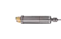
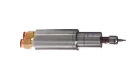
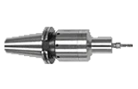
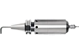
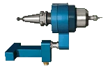
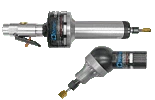
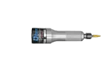
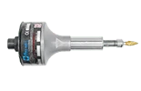
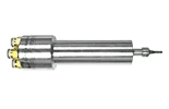
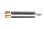
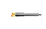
Figure 1: A clean airline from a filter/regulator to an Air Turbine hand tool with slide valve.
Install a new dedicated clean air line from a filter/regulator to your Air Turbine Tool® as shown in figure 1. Air supply must be clean and dry at 90 psi (6.2 bar) pressure with the specified volume CFM for your model as shown in figure 3 available on demand. A 0.3 micron filter/regulator/extractor combination is a recommended accessory to operate Air Turbine Tools® to eliminate all impurities in your air supply.
| Hose/Connector Minimum Required Internal Diameter |
|||
| Model | Metric | Imperial | |
|
| 4.763 mm | 3/16" |
|
| 6 mm | 15/64” |
|
| 8 mm | 5/16” |
| 10 mm | 25/64” | |
| Air Hoses and Fittings Requirements for Air Turbine Tools® | ||
| Model | Metric | Imperial |
| 4.763 mm | 3/16" |
| 6 mm | 15/64” |
| 8 mm | 5/16” |
| 10 mm | 25/64” |
Figure 2: Air Turbine Tools® hose /fitting /connector internal diameter specifications.
Air Hoses and Fittings Requirements
Avoid fittings, couplings and hoses with a smaller internal diameter than the minimum required for your model. Any connections smaller than the minimum will restrict air flow and reduce power to your Air Turbine Tool®.
You can find the minimum required internal diameter (ID) for fittings and hoses for your tool on the table shown below in figure 2.
Air flow restrictions (such as air leaks and obstructions) will cause underpowered performance and drag your tool through the material, damaging the bearings. Some fittings with nominal internal dimensions may have an ID passage that is smaller than stated and restrict air flow and power. It only takes one fitting with an internal diameter that is too small to reduce air flow and power of your Air Turbine Tool®.
Air Requirements
Ensure there is sufficient volume of clean compressed air flow at 90 psi/6.2 bar with the specified air flow volume CFM (L/s) for your model as shown in figure 3 to maintain working air consumption. Our governor increases air flow volume on demand to keep rotation at the high speed when your tool starts to cut. Air pressure and flow volume must therefore be available on demand and remain constant with no drop over time or when cutting.
Do not oil or lubricate. Use dry, clean, oil free 90 psi (6.2 bar) air supply only.
Avoid pressure below 90 psi (6.2 bar), which causes the tool to be dragged through the material, causing rapid bearing wear and underpowered performance. Do not use more than 100 psi (6.9 bar) pressure which will burst the turbine power producer.
Air pressure and flow must remain constant, with no drops under cutting load. Insufficient flow will cause the rotation of your tool to slow or stop suddenly, damaging the bearings. If a drop in psi (bar) occurs below 90 psi (6.2 bar), your compressor may not have enough CFM (L/s) to power the Air Turbine Tool® or there is a flow restriction in the air line.
Idle CFM/L/s Rating vs. Working Air Consumption Ratings
Air Turbine Tools® consume more air as the cutting load or the amount of material removed increases. This is normal operation of our patented governor which maintains high speed on your tool path and makes Air Turbine Tools® efficient in air consumption.
If you see the pressure on the dial in your regulator drop below 90 psi (6.2 bar) when your tool is working, that means you have insufficient air flow reaching your tool. This indicates that a coupling is restricting flow or your compressor is delivering less than the required air flow volume.
| Air Turbine Tools® Idle and Working Air Consumption Ratings |
|||
| Model | Speed | Air Consumption Idle | Air Consumption Working Flow |
| 40,000 RPM | 3.2 CFM (1.51 L/s) | 4.7 CFM - 7 CFM (2.22 L/s - 3.3 L/s) |
| 50,000 RPM | |||
| 65,000 RPM | 4 CFM (1.89 L/s) | ||
| 50,000 RPM | 4 CFM (1.89 L/s) | 6 CFM - 9 CFM (2.22 L/s - 4.24 L/s) |
| 40,000 RPM | 3 CFM (1.41 L/s) | 4.8 CFM - 7 CFM (2.27 L/s - 4.24 L/s) |
| 50,000 RPM | 4 CFM (1.89 L/s) | ||
| 65,000 RPM | |||
| 90,000 RPM | 5 CFM (2.37 L/s) | ||
| 30,000 RPM | 10 CFM (4.72 L/s) | 11 CFM - 20 CFM (5.19 L/s - 9.44 L/s) |
| 40,000 RPM | 13 CFM (6.14 L/s) | ||
| 50,000 RPM | 14 CFM (6.61 L/s) | ||
| 65,000 RPM | |||
| 30,000 RPM | 10 CFM (4.72 L/s) | 11 CFM - 20 CFM (5.19 L/s - 9.44 L/s) |
| 40,000 RPM | 13 CFM (6.14 L/s) | ||
| 40,000 RPM | 6 CFM (2.83 L/s) | 7 CFM- 10 CFM (3.3 L/s -4.27 L/s) |
| 50,000 RPM | |||
| 30,000 RPM | 12 CFM (5.66 L/s) | 12 CFM - 20 CFM (5.66 L/s - 9.44 L/s) |
| 40,000 RPM | 16 CFM (7.55 L/s) | ||
| 30,000 RPM | 13 CFM (8.97 L/s) | 22 CFM - 30 CFM (10.38 L/s - 14.16 L/s) |
| 40,000 RPM | 20 CFM (9.44 L/s) | ||
| 25,000 RPM | 13 CFM (6.14 L/s) | 19 CFM - 40 CFM (6.61 L/s - 16.52 L/s) |
| 30,000 RPM | 18 CFM (8.49 L/s) | ||
| 40,000 RPM | |||
| 25,000 RPM | 14 CFM (6.61 L/s) | 19 CFM - 40 CFM (8.97 L/s - 18.89 L/s) |
| 30,000 RPM | 20 CFM (9.44 L/s) | ||
| 40,000 RPM | 23 CFM (10.85 L/s) | ||
| Air Turbine Tools® Idle and Working Air Consumption Ratings |
| Model |
|
|
|
|
|
|
|
|
|
|
| Speed | Air Consumption Idle | Air Consumption Working Flow |
| 40,000 RPM | 3.2 CFM (1.51 L/s) | 4.7 CFM - 7 CFM (2.22 L/s - 3.3 L/s) |
| 50,000 RPM | ||
| 65,000 RPM | 4 CFM (1.89 L/s) | |
| 50,000 RPM | 4 CFM (1.89 L/s) | 6 CFM - 9 CFM (2.22 L/s - 4.24 L/s) |
| 40,000 RPM | 3 CFM (1.41 L/s) | 4.8 CFM - 7 CFM (2.27 L/s - 4.24 L/s) |
| 50,000 RPM | 4 CFM (1.89 L/s) | |
| 65,000 RPM | ||
| 90,000 RPM | 5 CFM (2.37 L/s) | |
| 30,000 RPM | 10 CFM (4.72 L/s) | 11 CFM - 20 CFM (5.19 L/s - 9.44 L/s) |
| 40,000 RPM | 13 CFM (6.14 L/s) | |
| 50,000 RPM | 14 CFM (6.61 L/s) | |
| 65,000 RPM | ||
| 30,000 RPM | 10 CFM (4.72 L/s) | 11 CFM - 20 CFM (5.19 L/s - 9.44 L/s) |
| 40,000 RPM | 13 CFM (6.14 L/s) | |
| 40,000 RPM | 6 CFM (2.83 L/s) | 7 CFM- 10 CFM (3.3 L/s -4.27 L/s) |
| 50,000 RPM | ||
| 30,000 RPM | 12 CFM (5.66 L/s) | 12 CFM - 20 CFM (5.66 L/s - 9.44 L/s) |
| 40,000 RPM | 16 CFM (7.55 L/s) | |
| 30,000 RPM | 13 CFM (8.97 L/s) | 22 CFM - 30 CFM (10.38 L/s - 14.16 L/s) |
| 40,000 RPM | 20 CFM (9.44 L/s) | |
| 25,000 RPM | 13 CFM (6.14 L/s) | 19 CFM - 40 CFM (6.61 L/s - 16.52 L/s) |
| 30,000 RPM | 18 CFM (8.49 L/s) | |
| 40,000 RPM | ||
| 25,000 RPM | 14 CFM (6.61 L/s) | 19 CFM - 40 CFM (8.97 L/s - 18.89 L/s) |
| 30,000 RPM | 20 CFM (9.44 L/s) | |
| 40,000 RPM | 23 CFM (10.85 L/s) |
Figure 3: Idle CFM (L/s) and working air consumption ratings.
Maintenance

Run The Tool Once A Month
Your Air Turbine Tool® must be run at least 10 minutes every 30 days from manufacture date to maintain optimal performance. Run at least 10 minutes before initial use. This will ensure the bearing lubrication does not solidify.
WARNING
Do not oil or lubricate Air Turbine Tools®. Use dry, clean, oil free 90 psi (6.2 bar) air supply only.
Do not oil or lubricate Air Turbine Tools®. Use dry, clean, oil free 90 psi (6.2 bar) air supply only.
Maintaining Your Air Supply
The airline must be impeccably clean with no coupling or hose smaller than the minimum internal diameter required for your model as described in figure 2.
Purge the airline of contamination before each use.
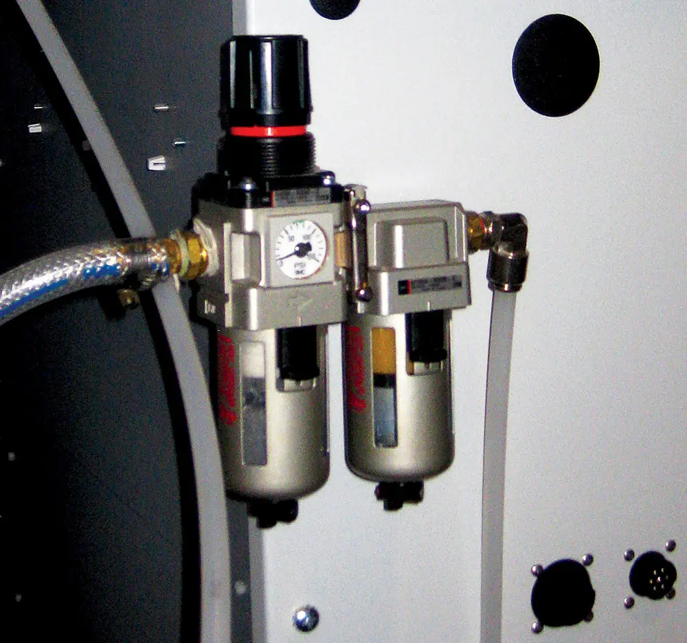
A 0.3 micron filter/regulator/extractor combination is a highly recommended accessory to operate Air Turbine Tools® to eliminate all impurities in your air supply. Contamination of your turbine components will damage your turbine and require repair. Filter elements need to be changed periodically, and the regulator and extractor must be drained in regular maintenance cycles.

Operation
Always monitor the air pressure gauge during operation of your Air Turbine Tool®. All tools are tested and rated to be within 10% of the designated speed. Do not try to cut too aggressively. You will overload your turbine causing your cutting tool to stall or drag in the material. Dragging your tool on the work or a sudden stop will cause stress to the bearings and force the grease out, causing premature failure.
WARNING
Purge the line of contamination and run for at least 10 minutes before initial use to ensure the bearing lubrication does not solidify.
Purge the line of contamination and run for at least 10 minutes before initial use to ensure the bearing lubrication does not solidify.
Selecting The Correct Cutting Tool
Ensure your cutting tool is rated for the rotational speed you are using. Your tool must be balanced and truly concentric to operate at the high speed of Air Turbine Tools®. Incorrect tool selection results in unbalanced rotation or overloading, which will result in stress on the bearings and premature failure.
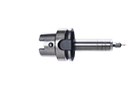
The stick-out extension length of the cutting tool from your collet should be no more than 3 times the diameter of the cutting tool from the collet as shown in figure 4 below.

Figure 4: Do not extend the cutting tool past 3 times the diameter of the cutting tool from the collet.

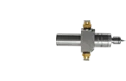
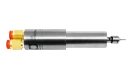
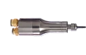
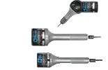
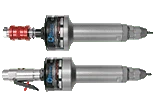
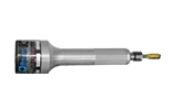
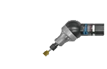
Figure 6: Using the slide valve on the 310RSV and the 310RXSV models to turn the Air Turbine Tool® on or off.
Properly Turning Your Tool On and Off
For SV units, slide the Slide valve open and closed. The ‘On’ position is always the position closest to your Air Turbine Tool®, while the ‘Off’ position is always the switch position furthest away from the tool. Certain models have a color-coded switch with green indicating ‘On’ and red indicating ‘Off’. Ensure that the Slide valve is always fully opened or closed as shown in figure 6.
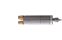
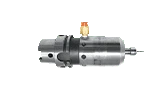
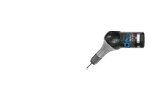
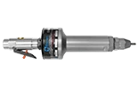
For DM units, simply squeeze the trigger switch to turn the tool on as shown in figure 7 below. The tool will only operate when the trigger switch is squeezed.

Figure 7: Using the trigger switch in all DM models to turn the Air Turbine Tool® on.
| Air Turbine Tools® HAVS Exposure Limits and Vibration Statistics |
| Models |
|
|
|
|
|
|
|
|
| Time to Reach EAV 2.5 m/s² A(8) | Time to Reach ELV 5 m/s² A(8) | Vibration Magnitude |
| 30 hours, 44 minutes | 122 hours, 53 minutes | 1.28 m/s² r.m.s |
| 128 hours, 15 minutes | 513 hours | 0.62 m/s² r.m.s |
| 34 hours, 44 minutes | 138 hours, 55 minutes | 1.20 m/s² r.m.s |
| 17 hours, 58 minutes | 71 hours, 50 minutes | 1.67 m/s² r.m.s |
| 24 hours, 28 minutes | 97 hours, 51 minutes | 1.43 m/s² r.m.s |
| 23 hours, 32 minutes | 94 hours, 6 minutes | 1.46 m/s² r.m.s |
| 64 hours, 11 minutes | 256 hours, 41 minutes | 0.88 m/s² r.m.s |
| 345 hours, 40 minutes | 1,382 hours, 37 minutes | 0.38 m/s² r.m.s |
Figure 8: HAVS exposure limits and vibration statistics for all models of Air Turbine Tools®. EAV represents the time to reach Exposure Action Value and ELV represents Exposure Limit Value.
Never Stall Your Tool
A sudden stop or stalling your hand tool will cause stress to the bearings and force the grease out of them.
Operate The Tool Safely
Comply with general industry safety & health regulations, part 1910 and 2206 OSHA, etc. Federal, state and local regulations and laws in your country. Ensure that you operate your Air Turbine Tool® in compliance with safety code for portable air tools – ANSI 186.1, etc. Refer to the table in figure 8 for the HAVS exposure limits for all models.
WARNING
Do not clamp Air Turbine Tool® hand tools into a fixture. This will cause distortion in the bearing race, damaging the tool.
Learn More About Air Turbine Tools®

Service & Support
Support is always available from our technical team in the USA and Germany. Repair Service is available in Florida and Munich. Call our factory technicians at +1-561-994-0500 or email us at [email protected].